Moog System 55 Modular Synthesizer
No longer available at zZounds
Forge brand-new sounds -- old-school style -- with the reissued Moog System 55. This analog modular synth is hand-built to the original 1973 specifications.
Overview
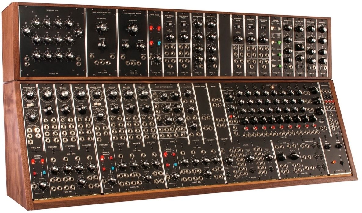
The Moog Modular System 55 is a highly sophisticated and dynamic analog instrument comprised of 36 handcrafted modules and housed in 2 hand-finished solid walnut cabinets. This magnificent creation provides limitless sonic potential and inspiration, while delivering the depth and dimension of sound found only in a vintage Moog modular synthesizer. The System 55 comes equipped with the coveted 960 Sequential Controller for incorporating extensive rhythmic complexity and expansion into the creative process.
Each System 55 is hand-built to its original 1973 Moog factory specifications and is a true recreation of the original. Individual modules are brought to life just as the originals were, by hand-stuffing and hand-soldering components to circuit boards, and using traditional wiring methods. Each module is then finished with a photo-etched aluminum panel, and placed in its new modular instrument.
This limited reissue of the Moog modular System 55 is built to order, and is available in highly limited quantities. Only 55 units will be made.
The basic cutoff frequency of the Low Pass Filter is determined by the combination of fixed control voltage and frequency range in addition to the control input signals. An increase in regeneration narrows and increases the strength of the cutoff frequency peak, while decreasing the amplitude of the lower frequencies.
The Frequency Range switch sets the overall range of frequencies covered by the Fixed Control Voltage potentiometer. The Low range encompasses 4hz to 20kHz, while the High range shifts 1 1/2 octaves up to 10Hz through 50kHz.
OFF: Delays are activated independently through individual trigger inputs.
PARALLEL: Trigger input to top 911A activates timing circuit on both simultaneously.
SERIES: Trigger input to top 911A activates top timing circuit then triggers second upon activation of first.
All manual controls on this module can be moved or switched during operation. This module functions as both an audio or control voltage generator.
Like the 921 Oscillator, this is one of the building blocks of analog synthesis. This oscillator generates both sub-audio and audio frequencies for control and audio signal use. The Frequency pot at the top of the module has a two-octave range for fine-tuning, while the Range switch shifts the frequency of the oscillator in octaves, up or down. Number indications on the Range switch correspond to traditional organ pipe range notations. Fixed level outputs for Sine, Triangle, Sawtooth and Rectangular waveforms are found at the right of the modules. DC Modulate is a linear frequency control input {does not conform to 1 volt/octave control voltage format}. AC Modulate input is a capacitor-coupled circuit like the DC Modulate input, however, blocking constant DC voltages.
921B Oscillators may be phase locked together via the Synch input jack and the associated three position Synch Switch. Phase locking capability is generally limited to the first six harmonics of the input signal. A sawtooth waveform is recommended for best synchronization results.
The sequencer module consists of a voltage controlled clock oscillator, which drives three rows of eight steps each. Indicator lights show sequence and step position status. A separate potentiometer for each step permits up to eight different voltage settings to be selected for each row. The DC voltage output corresponds to the column of pots below the lighted stage. Voltage range switches for each row determine the DC voltage range of each pot with two volts {X1}, four volts {X2}, or eight volts {X4} maximum extent. Two parallel outputs are provided for each row. Jacks for trigger inputs and outputs appear below each column. Trigger inputs activate that stage independently of the clock oscillator trigger. Trigger outputs are available for any other V-trigger activated input. Manual trigger buttons as well, are included for each of the eight stages {found below the V-trigger jacks}. Switches found immediately below each step position permit normal, skip or stop functions. A ninth position providing skip {continuous progression through the eight steps} or stop {one progression to closure} functions is included at the end of the row. Timing control for the eight steps is accomplished via the Third Row Control of Timing switch. This switch connects the third row of the sequencer into the control input of the clock speed for each stage according to the settings on the third row potentiometers. The Shift input admits an external clock input to the sequencing circuit. This input may be used in addition to or exclusive of the internal clock oscillator trigger. Manual shift from step to step is accomplished with the button next to the shift input jack, as well as individual manual trigger buttons for each step found under each step column.
Manual buttons or external v-trigger sources initiate the clock oscillator start and stop functions. The clock oscillator is capable of producing frequencies from .1Hz to 1kHz. It has both octave {range} and vernier {fine adjust} controls. One control input jack is available, as well as one rectangular wave output {approximately 90/10% duty cycle}. The clock oscillator, like other Moog oscillators, is standardized to one volt per octave.
The Audio to V-trigger circuit generates V-triggers when the audio input level rises above the threshold set on the Sensitivity potentiometer. This V-trigger sensitivity varies with the frequency band of the audio signal and with the frequency of its amplitude peaks. V-trigger duration is commensurate with the length of time the audio signal remains above the sensitivity threshold. Two parallel V-trigger outputs are included.
The S-trigger to V-trigger circuits converts any Short-to-ground trigger input to a v-trigger output.
Each V-trigger In to S-trigger Out circuit has two columns of six jacks each for input triggers and one S-trigger output. Column A of the V-trigger inputs will convert V-trigger signals to S-triggers with duration equal to the input. Column B determines S-trigger duration by the Switch-on-time knob ONLY. B Column S-triggers will block, extend or fore-shorten Column B V-trigger inputs to conform to whatever duration is indicated on the B-column potentiometer. A minimum switch- on-time of 40 milliseconds and maximum time of 4 seconds duration is available. Simultaneous inputs to both A and B columns may be made. Simultaneous inputs to two parallel jacks will result in the longer of the two trigger signals being accepted.
Faithfully Recreating the System 55
Over the course of 3 years, Moog Music set out to research and build a faithful recreation of the classic Moog modular System 55. Using all original documentation as well as circuit board and art files for every module, Moog Engineers have painstakingly recreated this incredible analog instrument.Each System 55 is hand-built to its original 1973 Moog factory specifications and is a true recreation of the original. Individual modules are brought to life just as the originals were, by hand-stuffing and hand-soldering components to circuit boards, and using traditional wiring methods. Each module is then finished with a photo-etched aluminum panel, and placed in its new modular instrument.
This limited reissue of the Moog modular System 55 is built to order, and is available in highly limited quantities. Only 55 units will be made.
Five 902 Voltage Controlled Amplifier Modules
The 902 voltage Controlled Amplifier is a differential… read more input and output circuit which gives an overall voltage gain of 2 {6dB} when the manual control potentiometer is at maximum {6}, or when a control voltage of 6 volts is applied to the control input. Maximum sum of control voltage {fixed control voltage and input jacks} is approximately 7.5 control volts, producing +4.7dB or gain of 3. Two modes of gain response are available: linear and exponential.903A Random Signal Generator Module
The Random Signal Generator produces continuous bursts of random frequencies and waveshape from approximately 25Hz to 20kHz. Two types of energy distribution are provided: white noise and pink noise. The former distributes amplitude evenly throughout the indicated audio spectrum- The latter reduces the amplitude of each frequency increment proportionally to produce equal energy per octave. Pink noise, thus, sounds "lower" in pitch to the ear.904A Voltage Controlled Low Pass Filter Module
The 904A Low Pass Filter attenuates frequencies above the fixed control voltage cutoff point at a rate of 24dB per octave. The cutoff point {cutoff frequency} is voltage controlled through the control input jacks. The sum of the applied control voltages doubles the frequency of the cutoff point for each one-volt increase {volt per octave standardization}. The regeneration potentiometer {variable Q} varies the amount of internal feedback, creating a resonant peak at the cutoff frequency. This resonant peak will break into oscillation at clockwise settings of the regeneration pot, creating a voltage controlled sine wave generator. The fixed control voltage pot covers a 12-volt {octave} range. The overall range of the FCV pot is determined by the Frequency Range switch, which moves the frequency cutoff range in two-octave steps.The basic cutoff frequency of the Low Pass Filter is determined by the combination of fixed control voltage and frequency range in addition to the control input signals. An increase in regeneration narrows and increases the strength of the cutoff frequency peak, while decreasing the amplitude of the lower frequencies.
904B Voltage Controlled High Pass Filter Module
The 904B Voltage Controlled High Pass Filter attenuates input signal frequencies below its nominal cutoff frequency setting. The attenuation below FCV cutoff setting is 24dB/oct. As the fundamental is generally the loudest frequency component of a complex tone, deletion of the lowest frequency range can radically alter the timbre. The FCV cutoff point is raised or lowered in octave per volt control inputs.The Frequency Range switch sets the overall range of frequencies covered by the Fixed Control Voltage potentiometer. The Low range encompasses 4hz to 20kHz, while the High range shifts 1 1/2 octaves up to 10Hz through 50kHz.
Five 911 Envelope Generator Modules
At the introduction of a switch-to-ground {S-trigger} trigger signal from an external source, the 911 Envelope Generator produces a single voltage contour whose time/voltage variation is determined by potentiometers T1, T2, T3 and a time constant sustaining level pot {Esus}. Closure of the input trigger switch directs the voltage contour to T3 {final decay} regardless of what stage { T1, T2 or E} was in current operation. The Envelope Generator requires an S-trigger to operate. External sources must be converted to the S-trigger format via the 961 Interface.911A Dual Trigger Delay Module
The 911A Dual Trigger Delay is designed to be used with 2 or more 911 Envelope Generators. It provides one or two time delays on an input trigger voltage - bound for the activation of an envelope switch trigger. Three different modes of operation are available via coupling mode switch:OFF: Delays are activated independently through individual trigger inputs.
PARALLEL: Trigger input to top 911A activates timing circuit on both simultaneously.
SERIES: Trigger input to top 911A activates top timing circuit then triggers second upon activation of first.
914 Fixed Filter Bank Module
Similar in function to the Moog 907A Fixed Filter Bank, the 914 Extended Range Fixed Filter Bank is a non-voltage controlled modifier with 14 separate passband controls: high pass, low pass and 12 center frequency knobs. Each passband range has an attenuation slope of 12dB per octave above or below the center frequency indicated 921 Voltage Controlled Oscillator: The 921 Voltage Controlled Oscillator is a variable waveform generator, which produces frequencies ranging from .01Hz to 40kHz. Four waveforms are available: Sine, Triangular, Sawtooth, and Rectangular {with variable duty cycle}. Both fixed and variable levels can be obtained from front panel output jacks. Nominal frequency is set manually by the scale, coarse range, frequency and {octave} range controls found at the top of the module. Voltage controlled rectangular width is set by the knob in the upper center {left}, with accompanying voltage input jacks. Clamping point {waveform reset control} may be set with the lower left knob and accompanying trigger inputs to the left. Multiple frequency control inputs can be plugged into this module in parallel. All waveform outputs can be used concurrently if desired.All manual controls on this module can be moved or switched during operation. This module functions as both an audio or control voltage generator.
Two 921A Oscillator Driver Modules
The 921A Oscillator Driver is a control voltage processor, which drives associated 921B oscillators through internally wired connections {via edge connectors}. Two voltages are generated: one for frequency control and one for rectangular wave duty cycle. Control inputs to this module change the frequency of its associated oscillators in volt/octave increments. Manual adjustment to the Frequency and Width Of Rectangular Wave pots changes the nominal frequency and duty cycle of all connected 921B's in parallel. Two ranges are provided on the Frequency potentiometer: semitone {two octaves compass} and octave {12 octaves compass} These ranges are selected by the white switch below the Frequency potentiometer. Control inputs for frequency and rectangular width are summing.Six 921B Oscillator Modules
The 921B Oscillator generates frequencies from 1Hz to 40kHz minimum. They are wired in groups to a common 921A Oscillator Driver, which provides both exponential frequency control and rectangular width voltage control.Like the 921 Oscillator, this is one of the building blocks of analog synthesis. This oscillator generates both sub-audio and audio frequencies for control and audio signal use. The Frequency pot at the top of the module has a two-octave range for fine-tuning, while the Range switch shifts the frequency of the oscillator in octaves, up or down. Number indications on the Range switch correspond to traditional organ pipe range notations. Fixed level outputs for Sine, Triangle, Sawtooth and Rectangular waveforms are found at the right of the modules. DC Modulate is a linear frequency control input {does not conform to 1 volt/octave control voltage format}. AC Modulate input is a capacitor-coupled circuit like the DC Modulate input, however, blocking constant DC voltages.
921B Oscillators may be phase locked together via the Synch input jack and the associated three position Synch Switch. Phase locking capability is generally limited to the first six harmonics of the input signal. A sawtooth waveform is recommended for best synchronization results.
960 Sequential Controller Module
The 960 Sequential Controller has a wide variation of functions, both as an independent module and in combination with the 961 Interface and 962 Sequential Switch.The sequencer module consists of a voltage controlled clock oscillator, which drives three rows of eight steps each. Indicator lights show sequence and step position status. A separate potentiometer for each step permits up to eight different voltage settings to be selected for each row. The DC voltage output corresponds to the column of pots below the lighted stage. Voltage range switches for each row determine the DC voltage range of each pot with two volts {X1}, four volts {X2}, or eight volts {X4} maximum extent. Two parallel outputs are provided for each row. Jacks for trigger inputs and outputs appear below each column. Trigger inputs activate that stage independently of the clock oscillator trigger. Trigger outputs are available for any other V-trigger activated input. Manual trigger buttons as well, are included for each of the eight stages {found below the V-trigger jacks}. Switches found immediately below each step position permit normal, skip or stop functions. A ninth position providing skip {continuous progression through the eight steps} or stop {one progression to closure} functions is included at the end of the row. Timing control for the eight steps is accomplished via the Third Row Control of Timing switch. This switch connects the third row of the sequencer into the control input of the clock speed for each stage according to the settings on the third row potentiometers. The Shift input admits an external clock input to the sequencing circuit. This input may be used in addition to or exclusive of the internal clock oscillator trigger. Manual shift from step to step is accomplished with the button next to the shift input jack, as well as individual manual trigger buttons for each step found under each step column.
Manual buttons or external v-trigger sources initiate the clock oscillator start and stop functions. The clock oscillator is capable of producing frequencies from .1Hz to 1kHz. It has both octave {range} and vernier {fine adjust} controls. One control input jack is available, as well as one rectangular wave output {approximately 90/10% duty cycle}. The clock oscillator, like other Moog oscillators, is standardized to one volt per octave.
961 Interface Module
Four independent circuits are found on the 961 Interface: one Audio-In to V- trigger Out circuit, one S-trigger In to V-Trigger Out circuit, and two V-trigger In to S-trigger Out circuits. All interface circuits may be used simultaneously, in combination, or separately.The Audio to V-trigger circuit generates V-triggers when the audio input level rises above the threshold set on the Sensitivity potentiometer. This V-trigger sensitivity varies with the frequency band of the audio signal and with the frequency of its amplitude peaks. V-trigger duration is commensurate with the length of time the audio signal remains above the sensitivity threshold. Two parallel V-trigger outputs are included.
The S-trigger to V-trigger circuits converts any Short-to-ground trigger input to a v-trigger output.
Each V-trigger In to S-trigger Out circuit has two columns of six jacks each for input triggers and one S-trigger output. Column A of the V-trigger inputs will convert V-trigger signals to S-triggers with duration equal to the input. Column B determines S-trigger duration by the Switch-on-time knob ONLY. B Column S-triggers will block, extend or fore-shorten Column B V-trigger inputs to conform to whatever duration is indicated on the B-column potentiometer. A minimum switch- on-time of 40 milliseconds and maximum time of 4 seconds duration is available. Simultaneous inputs to both A and B columns may be made. Simultaneous inputs to two parallel jacks will result in the longer of the two trigger signals being accepted.
962 Sequential Switch Module
The 962 Sequential Switch selects between two or three signal inputs, coupling one signal to the output jack at a time. A V-trigger pulse introduced to the Shift Input initiates the sequence. The Sequential Switch will alternate between stages One and Two, disregarding stage three until a standard {tip-sleeve} phone plug is patched into Signal Input Three. A connection to Input Three will cause the Sequential Switch to alternate between the three stages {in order) when triggered. Separate V-trigger input and output jacks are provided far each of the three stages, as well as buttons for manual switching. A small light for each stage indicates its status, on {coupled to the output} or off.992 Control Voltage Panel
The 992 Control Voltage Panel is used for routing up to four control voltage signals to the 904B Low Pass Filter. The fourth input on the panel contains a signal inverting attenuator circuit.993 Trigger and Envelope Voltages Panel
The Trigger and Envelope Voltages Panel is a signal routing module for S-triggers coming from one or two controllers. Lighted switches labeled "FROM 1" and "FROM 2" at the top of the panel connect the controller trigger outputs (when lighted) to the 911A Dual Trigger Delay. The lower three left hand column switches route the trigger signal as follows: top switch - to left 911 with no delay, center switch - to center 911 with delay set by top 911A delay unit, bottom switch - to the right 911 with delay set by the bottom 911A. The right hand green switches connect the DC control voltages from the 911's to their respective 902 Voltage Controlled Amplifiers: Left to left, center to center, right to right.994 Dual Multiples Panel
The multiple is a device, which permits multiple distribution of one signal to several different places. This process is often called signal splitting. Multiples are used for many purposes; from linking two patch cords together, sending a single signal to several different modules at the same time, to doubling or trebling the amplitude of a signal by sending it X3 to a particular source.995 Attenuator Module
Attenuators reduce the gain or amplitude of any applied input signal, control or audio. Moving clockwise from zero gain to unity with input, these attenuators can be used for reducing the effect of a control upon a voltage controlled module, providing up to three variable outputs from a single source input or reducing the gain of an entire signal complex.Three CP3A Console Panels
The CP3A module has four varied functions. The primary circuit is a 4x1 mixer with positive and negative outputs and a maximum gain of 2x. This mixer can combine both AC and/or DC voltages. The second series of functions are four signal routing switches, which connect the incoming control voltages from keyboard, ribbon or other controller units to the frequency control input of associated oscillator drivers found directly above the switching panel. The fourth input switch has both an external input jack and attenuator {found directly below}. This input jack is connected to the Oscillator Driver when the associated switch is on and the attenuator set above zero. At "10" a signal introduced here will be equal to one which is introduced directly into the frequency control inputs found on the Oscillator Driver itself. The two final elements found on the CP3A are a multiple {signal splitting -- one input becomes three} and trunk line jacks, which carry a signal to the rear of the synthesizer. read lessSpecs
- Main Cabinet: Weight: 100 lbs., Dimension: 48 1/2" wide x 15 1/2" high x 14" deep
- Upper Cabinet: Weight: 60 lbs., Dimension: 48 1/2" wide x 10" high x 8 1/2" deep
- 1x 903A Random Signal Generator
- 1x 904A Voltage Controlled Low Pass Filter
- 1x 904B Voltage Controlled High Pass Filter
- 5x 911 Envelope Generators
- 1x 911A Dual Trigger Delay
- 1x 914 Fixed Filter Bank
- 1x 921 Voltage Controlled Oscillator
- 2x 921A Oscillator Drivers
- 6x 921B Oscillators
- 1x 960 Sequential Controller
- 1x 961 Interface
- 1x 962 Sequential Switch
- 1x 992 Control Voltage Panel
- 1x 993 Trigger and Envelope Voltages Panel
- 1x 994 Dual Multiples Panel
- 1x 995 Attenuator
- 1x CP2 Console Panel
- 3x CP3A Console Panels
- 1x CP8 Console Panel
- 1x 350 Watt 120 VAC or 230 VAC Switch Selectable Power Supply
Included Patch Cabling:
- 14x - 1' 1/4" TS cables
- 12x - 2' 1/4" TS cables
- 12x - 3' 1/4" TS cables
- 6x - 4' 1/4" TS cables
- 4x - 5' 1/4" TS cables
- 2x - 1' S-Trigger cables
- 3x - 3' S-Trigger cable
- 1x - 'Y-cable' S-Trigger
- Upper Cabinet: Weight: 60 lbs., Dimension: 48 1/2" wide x 10" high x 8 1/2" deep
System 55 Modules:
- 5x 902 Voltage Controlled Amplifiers- 1x 903A Random Signal Generator
- 1x 904A Voltage Controlled Low Pass Filter
- 1x 904B Voltage Controlled High Pass Filter
- 5x 911 Envelope Generators
- 1x 911A Dual Trigger Delay
- 1x 914 Fixed Filter Bank
- 1x 921 Voltage Controlled Oscillator
- 2x 921A Oscillator Drivers
- 6x 921B Oscillators
- 1x 960 Sequential Controller
- 1x 961 Interface
- 1x 962 Sequential Switch
- 1x 992 Control Voltage Panel
- 1x 993 Trigger and Envelope Voltages Panel
- 1x 994 Dual Multiples Panel
- 1x 995 Attenuator
- 1x CP2 Console Panel
- 3x CP3A Console Panels
- 1x CP8 Console Panel
- 1x 350 Watt 120 VAC or 230 VAC Switch Selectable Power Supply
Included Patch Cabling:
- 14x - 1' 1/4" TS cables
- 12x - 2' 1/4" TS cables
- 12x - 3' 1/4" TS cables
- 6x - 4' 1/4" TS cables
- 4x - 5' 1/4" TS cables
- 2x - 1' S-Trigger cables
- 3x - 3' S-Trigger cable
- 1x - 'Y-cable' S-Trigger
Documents and Manuals
For support or warranty questions, please contact the manufacturer:
Phone: 828-251-0090
Email: techsupport@moogmusic.com
Web: https://moogmusicsupport.zendesk.com
Phone: 828-251-0090
Email: techsupport@moogmusic.com
Web: https://moogmusicsupport.zendesk.com
No longer available at zZounds
In most cases, a product is unavailable because it has been discontinued by the manufacturer

This is a carousel with product cards. Use the previous and next buttons to navigate.
People who bought this item also bought
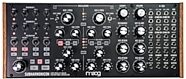
Moog Subharmonicon Desktop Analog Synthesizer
$599.00
- 12 x$49.92
- 8 x$74.88
- No Credit Check6 x$99.83
- No Credit Check4 x$149.75
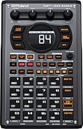
Roland SP-404MKII Sampling Workstation
$499.99
- 8 x$62.50
- No Credit Check6 x$83.33
- No Credit Check4 x$125.00
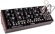
Moog Mother-32 Semi-Modular Analog Synthesizer
$599.00
- 12 x$49.92
- 8 x$74.88
- No Credit Check6 x$99.83
- No Credit Check4 x$149.75
Roland JU-06A Boutique Series Synthesizer
$399.99
- 8 x$50.00
- No Credit Check6 x$66.66
- No Credit Check4 x$100.00
Moog DFAM Drummer From Another Mother Semi-Modular Analog Percussion Synthesizer
$599.00
- 12 x$49.92
- 8 x$74.88
- No Credit Check6 x$99.83
- No Credit Check4 x$149.75
Fender American Pro II Precision Electric Bass, Maple Fingerboard (with Case)
$1,849.99
- 12 x$154.17
- 8 x$231.25
Native Instruments Kontrol S88 MK3 USB MIDI Keyboard Controller, 88-Key
$1,299.00
- 18 x
- 12 x$108.25
- 8 x$162.38